


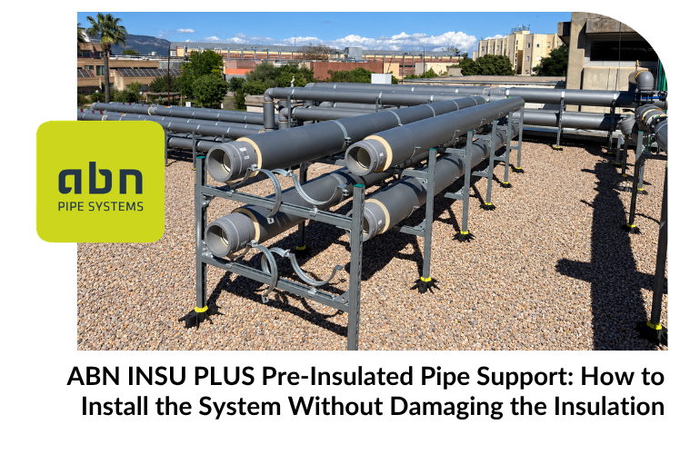
Support for pre-insulated pipes must keep the pipework stable while protecting the insulation and outer jacket. In ABN INSU PLUS, the inner pipe, PUR foam insulation and outer jacket form a complete assembly. Supports must therefore be selected according to the dimensions and operating conditions of the whole system, rather than the inner pipe diameter alone.
The configuration varies depending on the model. For example, the ABN// PPR CT INSU-PE model combines an inner PP-RCT RP pipe, PUR HFO foam insulation, and an outer polyethylene jacket. The INSU-AL variant uses an aluminum outer jacket. The support solution must be compatible with the selected product reference and the project’s installation specifications.
Why Correct Support for Pre-Insulated Pipes Matters
Supports hold the pipe in place along its route and transfer its load to the structure. Improper fastening can cause displacement or damage the outer surface. If pressure is concentrated at a single point, it can also affect the insulation beneath the jacket.
The fastener must hold the assembly in place without piercing or deforming it. Avoid sharp edges, screws, or other elements that could mark the jacket, and do not overtighten the clamp. The contact surface and the diameter of the fastener must be compatible with the actual external dimensions of the pre-insulated assembly.
Size the support for the entire system
Before selecting clamps, verify the part number and the outside diameter of the pre-insulated pipe. The nominal inside diameter is not sufficient: the foam and the jacket increase the overall dimensions of the assembly and must be taken into account in the installation details.
To determine the support requirements for pre-insulated pipes, the design may need to consider the diameter, the weight of the pipe when filled with fluid, the temperature, the orientation of the run, changes in direction, and the loads from fittings. The spacing between supports must comply with the technical documentation applicable to the entire system and the specific conditions of the installation.
Do not automatically apply a clamp spacing specified for an uninsulated interior pipe to a pre-insulated assembly. If the table you are consulting does not specify that it applies to INSU PLUS, confirm the criteria with the technical team before using it on site.
Coordinates fixed points and guide supports
A layout may combine fixed points and supports that allow for the movement intended by the design. Their placement must be coordinated with the layout, expansion joints, changes in direction, fittings, and connections to equipment.
Do not indiscriminately block all sections. The layout must follow the plan defined for the installation, so that each support fulfills its intended function. Valves, Collectors, and other heavy fittings may require their own support, depending on the project, so that their weight is not unduly transferred to the pipe or a joint.
If the installation falls under the scope of the RITE, check the requirements applicable to the project in the Regulation on Thermal Installations in Buildings.
Best Practices During Assembly
Before securing each section, check that the clamp or support is compatible with the sleeve and the system’s outer diameter. During installation:
- Avoid drilling or cutting into the shirt to secure the pipe.
- Do not tighten the clamp so much that it deforms or marks the lining.
- Avoid placing the device on surfaces with sharp edges or surfaces that could damage the outer casing.
- Make sure the pipe is aligned and that the supports are secured to a suitable structure.
- Follow the pattern of fixed points and guide supports defined for the route.
- Check elbows, branches, and connections to equipment to ensure that their loads are properly supported.
These guidelines help prevent damage during installation, but they do not replace the technical data sheet or the approved support details for each project.
Check the layout before shutting down the facility
After installing the supports, perform a visual inspection to check for any marked sleeves, misaligned sections, or fasteners that do not conform to the plan. Also verify that the insulation is protected at the support points and that the joints and fittings have been installed according to the system instructions.
For vertical sections, changes in direction, large diameters, or points with concentrated loads, the layout must be analyzed during the design phase. Reviewing it in advance can prevent modifications once other installations have already occupied the space.
Check out the solution for your project
At ABN Pipe Systems, we manufacture the ABN INSU PLUS system and its fittings in Spain. The part number, diameter, outer jacket, and route all influence the support solution that must be determined.
If you are planning an installation, please send us the floor plan or any available information so we can review the system and recommend the appropriate mounting solution. You can call us at 981 148 425 or email us at info@grupoabn.com.
